Table of Contents
PRPL Code Segments
Here I go over some PRPL code segments, each achieving some particular task (like moving a units/ships, creating units/particles, showing images or text, discovering units/ships/particles, input handling etc.). Each segment isn't enough to make a fully functional unit, but most units consist of several such segemnts working together.
If you are looking for what is possible in PRPL or some inspiration for your own units, this is a good place to start, provided you know the fundamentals. Each segemnt will consist of the code doing the work, the explaination of the code and a little homework for you to modify it in some way.
(TODO: buildable/charable unit, creating a unit, work with images, work with text, communication betwee n scripts, work with ship inventory - this list is mostly for myself so I don't forget what I wanted to talk about)
Discovering units/ships/particles in a range
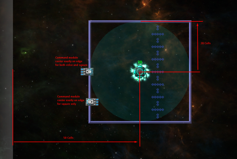
Let's start with “discovery” commands, since we will learn about cell and pixel coordinates, which will be usefull later. Let's start with GetAllShipsInRange # [int int float bool - list] (x y range square?). The first 2 arguments are the cell coordinates for the center of the search, next is the range of the search (in cells) and the final argument is the search mode (1=square, 0=circle). Let's look at a visual example:
50 50 20 0 GetAllShipsInRange ->list
Here, we are looking for all ships in a cirlce centered at cell (50,50) with radius 20. The search area is visualized exactly with the range of the energy source. As noted in the comment, the center of the command module has to be in the range for the ship to be considered in range.
The (50,50) detonate the coordinates of the cell at the center of the search. when wrtitng coordinates as a pair, X is always first and Y is always second. The bottom-left cell has coordinates (0,0), you can also see the coordinates of the cell where your mouse on the bottom of your screen (left of the mid-bottom panel).
Lastly, if the mode was set to square, the area would be a square with side length 2*length as shown in the image.
You can also discover units in the same way using GetAllUnitsInRange # [int int float bool - list], and there is also GetClosesShipInRange # [int int float bool - int] that works, simmilarly, but only returns the id of the closest ship in the search range, or -1 if no ship is found.
Particle discovery commands
Particle discovery works in a completely different way. First, GetParticlesInRange # [int int float bool bool - list] (x y range square? enemy?) takes additional parameter: wheter to look for enemy particles or friendly (1=enemy, 0=friendly).
Moreover, range is now the diameter rather than the radius of the search (the diameter of the circle, or the side length of the square, depending on the mode), but you can still use GetParticlesInRadius if you want to use radius.
Lastly the coordinates for the center of the search as well as the search diameter/radius are now in pixels. Pixels are like cells, except they form a denser grid. The easy conversion is that 1 cell = 4 pixels, so for example the pixel equivalent of cell (10,20) would be (40,80). Ecxept, that is not entirely the case.
Cell coordinates vs pixel coordinates
Cell coordinates are always integers, and a cell coordinate always refer to the cell as a whole. Pixel coordinates, however, are float and they refer to a specific point on the game map. For example, (4.2,5) and (4.3,5) are different pixel coordinates, since they are different points on the game map, however (4.2,5) and (4.3,5) are the same cell coordiantes since they are converted to the same cell (4,5).
So, when I say that “1 cell = 4 pixels isn't entirely accurate”, what I mean is that if you take a cell coordinate and just multiply both components by 4, you will get a pixel coordinate refering to the bottom-left corner of the cell. If you want a pixel coordinate representing the center of the cell, you need to multiply the cell coordinates by 4 and then add 2.
The homework
Write a script that will find all units and enemy particles withing 20 cells distance from itself. (Use CurrentCoords # [ - int int] and CurrentPixelCoords # [ - float float] to get the current pixel/cell position of the PRPL core running the script.)
Solution:
<html></html>
Moving a unit
Moving a unit to a target position isn't nearly as simple as you might think. Here is the full code:
$Speed:2.0 #Move $Speed pixels per frame
$TargetX:202 #Pixel X of the target position
$TargetY:82 #Pixel Y of the target postiion

CurrentPixelCoords ->y ->x #save current position
<-x <-y <-TargetX <-TargetY Distance ->distance #distance to target, in pixels
<-distance <-Speed lte if #if the target is withing the reach, teleport there outright
    Self <-TargetX 4 div <-TargetY 4 div SetUnitCoords
    Self <-TargetX <-TargetY SetUnitPixelCoords
    "Finished moving" Trace
else
    #move $Speed pixels closer to the target
    <-TargetX <-x sub <-distance div <-Speed mul <-x add ->x
    <-TargetY <-y sub <-distance div <-Speed mul <-y add ->y
    Self <-x 4 div <-y 4 div SetUnitCoords #set cell coordinates
    Self <-x <-y SetUnitPixelCoords #set pixel coordinates
endif
We start relatively simply by first saving the current pixel coordinates and then computing the distance t othe targer. If the target is close enough (closer than $Speed), it means that the unit can move to the targer in this frame, so we do just that.
The more interesting is how we move the units closer if it's far ways. First, <-TargetX <-x sub is the “X distance” from the current core to the target. If we were to add this to the X position, it would move to the target directly. So we divide this by distance. That way we only move 1 pixel closer to the target. Finally, we multiply by Speed to move Speed pixel closer to the target. … <-x add ->x Will then move the core by the specified amount.
Some image might be more helpful:
The image explains the expression <-TargetX <-x sub <-distance div <-Speed mul and why adding it to the X position (and same with Y) will move the unit Speed pixels closer to the target. Then, <-x add ->x simply increases the position by that amount, moving the unit closer to the target.
Few important notes:
SetUnitCoordswill also set the pixel coordinates coresponding to that cell, so it's important to call this first.SetUnitCoordswill convert the cell coordinates as integers, so it's important to move the unit alongside the pixel coordinates instead.- Notice that the target is
(202,82). This is very much on purpouse, as that pixel coordiantes are at the center of the cell(50,20).
Homework
Make a unit that accelerate towards the target point instead. Isntead of $Speed use $Accel and increase the speed by that amount every frame.
Solution:
Making a buildable & chargable unit
Here is a code for making a unit that first needs to be build with lathes and then once build accepts energy from nearby energym mines (or ships with energy port).
$MaxHealth:200
$MaxEnergy:100

once
    #healt
    Self <-MaxHealth SetUnitMaxHealth # lathes will heal 1 health per frame
    Self 0 SetUnitHasHealthBar # don't display healtb bar while it has only 1 health at start
    Self -1 SetUunitLatheDamageAmt # negative value - lathe heals the unit
    Self 1 SetUnitLatheTargets # make lathes target this unit

    #energy
    Self 0 SetUnitReceivesPackets # set 0 for now, so it doesn't accept enemy packets
    Self <-MaxEnergy SetUnitMaxEnergy
    Self 3 SetUnitPacketDelay # accept 1 energy packet every X frames
    Self 0 SetUnitHasEnergyBar # hide energy bar for now

    #reset
    Self 1 SetUnitHealth # start at 1 health - it would destroy itself at 0
    Self 0 SetUnitEnergy # reset energy to 0
    Self 1 SetUnitIsEnemy # make the unit enemy, so that friendly lathes will target it and heal it
endonce

Self GetUnitIsEnemy if
    #while "constructing" with lathe

    #display health bar only if health > 1
    Self GetUnitHealth 1.5 lt if
        Self 1 SetUnitHealth # work around some wierd float calcualtion issues
    else
        Self 1 SetUnitHasHealthBar # show energy bar once it's being "constructed" by the lathes
    endif

    #flip to gather energy when built
    Self GetUnitHealth gte (Self GetUnitMaxHealth) if # check if at full health
        Self 0 SetUnitIsEnemy # make unit no longer enemy, so it can receive friendly energy
        Self 1 SetUnitReceivesPackets # receive friendly energy packets
        Self 0 SetUnitHasHealthBar # hide health bar once it's build
        Self 1 SetUnitHasEnergyBar # show energy bar isntead
        Self 0 SetUnitLatheTargets # so enemies don't destroy it once built
    endif
else
    # already build
    Self GetUnitEnergy gte (Self GetUnitMaxEnergy) if # check if at full energy
        "Full energy!" Trace #todo: actaully do something useful here
        Self 0 SetUnitEnergy #reset energy back to 0
    endif
endif
Now that's a lot of code, but the comments should explain it well enought. The only wierd bit might be hiding/showing the ehalth bar. It is hidden at first, because it would render a tiny red dot when the unit is at 1 health, which wouldn't look very nice, since the unit starts at 1 health even before yo ustart building it with lathes.
You can go and make it do something usefull once it cahrges with energy, or you can remove the nergy reset and have it provide a pasive bonus while at full energy, the possibilites are endless.
Homework
Change the unit to be symetrical for both the player and the enemy - once the player captures it with lathes, the enemy can capture it as well. When in enemy control, make the unit accept enemy energy packets and up build energy as well. Finally, make the health go from 100% to 0% when being captured by the lathes, as that would more suit a flipable unit like this.
Working with images
Let's try a new format - we will start with a simple script of showing a star image, and then we will add new features gradually. So, here is the basics of adding an image: First, create the image you want. It must have exactly one if the following sizes: 64×64 pixels, 128×128 pixels, or 256×256 pixels. You download the 2 images used in this tutorial right here:
<html>
</html>
(It's a white image on a transparent background, so some images viewers might display it as a white square, but don't worry, it will work fine).
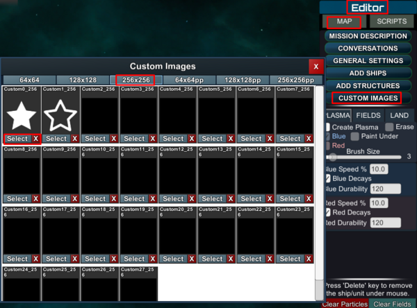
Next, you need to register the images into the game. In the PF map editor, go to Editor -> Map -> Custom Images -> 256×256 tab -> Select on the first slot, and then open the downlaoded file in the file chooser.
Finally, once the images are loaded into the game, you can write a PRPL script that will use the images:
$StarFill:"Custom0_256"
$StarBorder:"Custom1_256"

once
    Self "fill" <-StarFill SetImage
    Self "fill" 255 255 0 255 SetImageColor # R=255 G=255 B=0 A=255 - yellow
    Self "fill" 2 2 SetImageScale

    Self "border" <-StarBorder SetImage
    Self "border" 255 128 0 255 SetImageColor # R=255 G=128 B=0 A=255 - orange
    Self "border" 2 2 SetImageScale
endonce
Again, search for “image” on the PRPL Reference for more detail, or go to the CRPL Reference if the page isn't filled on the PRPL wiki.
The interesting part here is that the image itself is whire, but the color is set in PRPL. The advantage over having the image itself colored is that we can now compute and change the color with PRPL to our liking, which we will do momentary.
But first, a few notes: Self "fill" <-StarFill SetImage The first agument, Self, is the ID of the core on which we want to set the image, so you can manipulate images on different cores, but that is rarely used. The second argument, "fill", is the internal name of the image. Since a PRPL core can have multiple images attached to them and you need to differentiate between them, this is the way to it. Finally, <-StarFill is the name of the image in the game's image repository (if you can call that). This is the slot name into which you loaded the image earlier. It's a good practice to always set this as Script Argument, since you could easily end up with 2 scripts that want to use the same slot for different images, so you can easily change the image slot without even editing the script's code.
Next, let's take a look at Self "fill" 255 255 0 255 SetImageColor The 4 numbers specify the color as a RGBA color - that means the first number is for Red, second for Green, third for Blue and fourth for Alpha (visibility). Each pixel's values in the original image is “multiplied” by this value (or rather, by it's relative value). For example, if the original pixel in the image had color (255,128,0,128) (half-transparent orange), and the color set by PRPL was (32,128,255,64), then the resulting color would be (64,128,0,32), since (32 = 255 * (32/256), 64 = 128 * (128/256), 0 = 0 * (255/256), 32 = 128 / (64/256)). Note that this can only decrese the color value, so while you can turn white into any other color, black will always remain black.
Finally, Self "fill" 2 2 SetImageScale is relatively simple, for image scale just remember that 1 scale = 3 cells, probably since 3×3 modules are a common image, so they would have scale 1.
Making the star change color
Now we are getting into some fun. Let's start by chaning the color from red to yellow by keeping the red color channel at 255 and changing the green color channel:
$StarFill:"Custom0_256"
$StarBorder:"Custom1_256"
$Step:2 #the speed of color change

once
    Self "fill" <-StarFill SetImage
    #Self "fill" 255 255 0 255 SetImageColor # R=255 G=255 B=0 A=255 - yellow
    Self "fill" 2 2 SetImageScale

    Self "border" <-StarBorder SetImage
    Self "border" 255 128 32 255 SetImageColor
    Self "border" 2 2 SetImageScale

    0 ->green
    1 ->growing #the green color is growing
endonce

<-growing if
    <-green <-Step add ->green
    <-green 255 gt if
        # the green color is more than the maximum value of 255
        255 ->green #set it back to maximum
        0 ->growing #make it so its growing smaller isntead
    endif
else
    <-green <-Step sub ->green
    <-green 0 lt if
        # the green color is less than the minimum value of 0
        0 ->green #set it back to minimum
        1 ->growing #make it so its growing larger again
    endif
endif

Self "fill" 255 <-green 0 255 SetImageColor
The code should be pretty self-explanatory. If you have never worked with RGb values before and ar ewondering where the 255 number comes from, it's from the fact taht computers store color as 3 8-bit numbers, one for Red, one for Green and one for Blue (RGB). And since 8 bits can hold 256 diffent values, the color values are from the range 0-255. Finally, if you want to see some examples of colors and their RGB values, jsut any online color picker.
Setting position and rotation
Next we are going to make the start rotate around the core by chaning it's position, as well as rotate as an image to make it spin. Code:
$StarFill:"Custom0_256"
$StarBorder:"Custom1_256"
$Step:2 #the speed of color change
$Distance:40 #the radius of the star's orbit around the core, in pixels
$OrbitingSpeed:0.01 #the speed at which the star orbits around the code, in radians/frame
$SpinningSpeed:-0.03 #the speed at which the star spins around it's own center, in radians/frame

once
    Self "fill" <-StarFill SetImage
    #Self "fill" 255 255 0 255 SetImageColor # R=255 G=255 B=0 A=255 - yellow
    Self "fill" 2 2 SetImageScale

    Self "border" <-StarBorder SetImage
    Self "border" 255 128 32 255 SetImageColor
    Self "border" 2 2 SetImageScale

    0 ->green
    1 ->growing #the green color is growing

    0 ->orbitAngle
    0 ->spinAngle
endonce

# set the color
<-growing if
    <-green <-Step add ->green
    <-green 255 gt if
        # the green color is more than the maximum value of 255
        255 ->green #set it back to maximum
        0 ->growing #make it so its growing smaller isntead
    endif
else
    <-green <-Step sub ->green
    <-green 0 lt if
        # the green color is less than the minimum value of 0
        0 ->green #set it back to minimum
        1 ->growing #make it so its growing larger again
    endif
endif

Self "fill" 255 <-green 0 255 SetImageColor

#set the position
<-orbitAngle <-OrbitingSpeed add ->orbitAngle
Self "fill" <-orbitAngle cos <-Distance mul SetImagePositionX
Self "fill" <-orbitAngle sin <-Distance mul SetImagePositionY
Self "border" <-orbitAngle cos <-Distance mul SetImagePositionX
Self "border" <-orbitAngle sin <-Distance mul SetImagePositionY

#set the rotation
<-spinAngle <-SpinningSpeed add ->spinAngle
Self "fill" <-spinAngle SetImageRotation
Self "border" <-spinAngle SetImageRotation
The key to making it look good is balancing the rotations speeds properly. I definetely like it more when the start is spinning in the oposite derection than the orbit (positiv/negative rotation speed), but you can change it however you like.
The homework
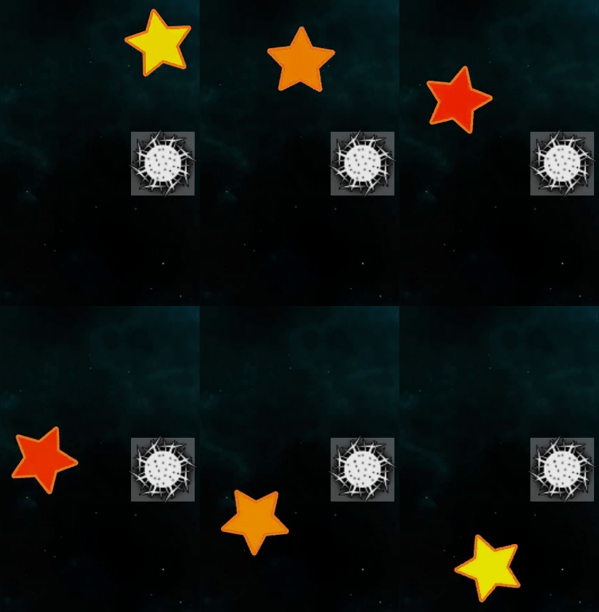
We could go on and on, making the star bigger/smaller, or moving it closer/further away, or even adding more interesting color changes, etc. But for the homework, make it so that 6 stars orbit the core, evenly spread out. You will need 12 image slots in total (6 for the “fills”, and 6 for the “borders”) and I recommend you name them “fill0”, “fill1” etc so you can easily manipulate them by using "fill" I concat inside a do-loop. Use TWOPI 6 div to get the radian equivalent of 60 degrees.
Preview:
Solution:

